
2JZ-GTE CEL error checking
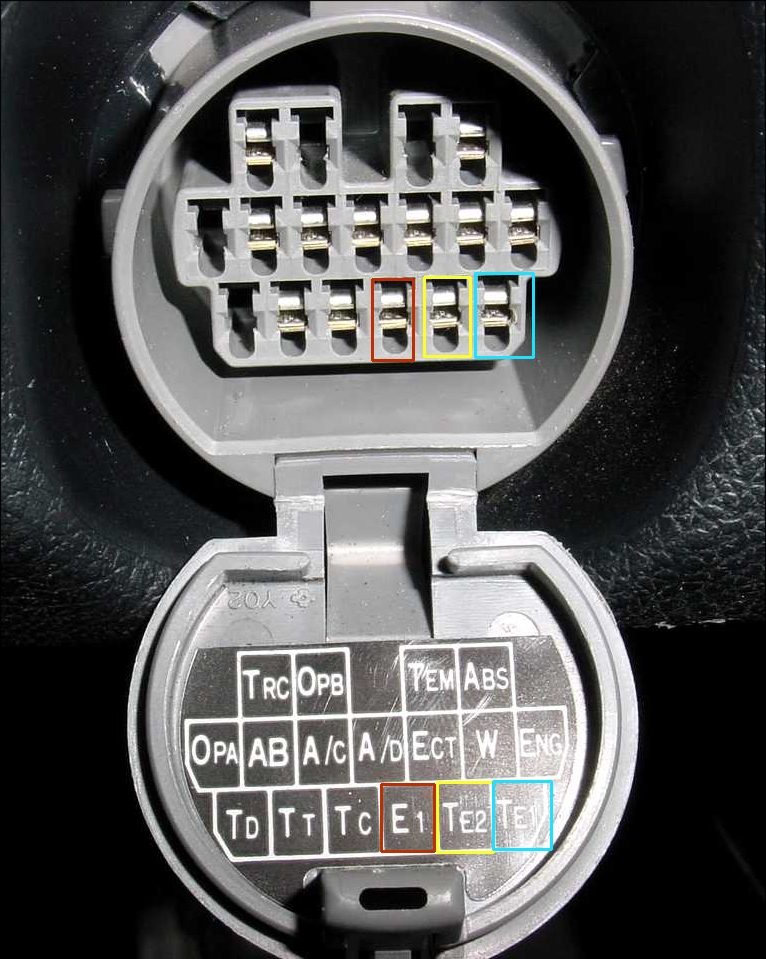
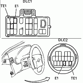
The ECU stores an error code so that you can check for problems. Rather than requiring a bug diagnostics machine, you can use a simple paperclip, or a short wire. You use this to bridge the connections E1 and TE1 in the diagnostics port. For VVT-i versions please use Tc and E1 as ODB2 engines (mid 1996+) use Tc and E1 instead.”
For OBD2 codes please use a compatible OBD2 Scanner. The paperclip method won’t work well for those ECU’s when searching for error codes.
Also, Make sure you have de-immobilised your car as some immobilisers stop the engine light from flashing.
Here are the different types of plugs displayed (images taken from other sites/google):
1JZ Supra/Soarer:


OBD1 Round plug:
Soarer plugs:
- Before proceeding, make sure the:
- CHECK ENGINE light circuit is functional. It should be ON when the ignition switch is ON with the engine stopped.
- Battery voltage is above 11 volts.
- Throttle valve is fully closed (Throttle Position Sensor IDL points closed).
- Accessory switches (A/C, etc.) are OFF.
- Engine is at normal operating temperature (if possible).
- Turn ignition switch to ON position.
- Do not start the engine.
- Place a jumper wire across TEl and El terminals in engine check connector.
- Count number of flashes from CHECK ENGINE light.
- If system is operating normally (with no detected faults), the CHECK ENGINE light will blink continuouslyand evenly about 2 times a second.
- Otherwise, the light will blink a number of times equal to the trouble code as follows:
- The light blinks only (.5 second ON, .5 second OFF) when indicating a number.
- The light will be OFF for 1.5 seconds between the first digit and the second digit of the code.
- If more than one code is stored, the light will be OFF for 2.5 seconds before the next code is displayed.
- Once all code(s) have been displayed, the light will be OFF for 4.5 seconds and then the whole sequence will repeat.
- The diagnostic code series will continue to repeat as long as the check connecter terminals TEl and El are connected.
- When finished, remove the jumper wire.
- After repairing the malfunction, clear the codes from the ECUs memory: Remove the EFI fuse (15A) for 30 seconds with the ignition switch OFF.
Most common 2JZ CEL codes chart:
| DIAGNOSTIC TROUBLE CODE CHART (2JZ-GTE) | ||||||
| DTC | Circuit | Diag.. Trouble Code Detecting Condition | Trouble Area | Normal Mode | Test Mode | Memory |
| No. | ||||||
| – | Normal | No code is recorded | – | – | – | – |
| 12 | G, NE Signal (No. 1) | No “NE” or “G1” and “G2 signal to ECM for 2 sec. or more after cranking. | Open or short in crankshaft position sensor, camshaft position sensor No. 1, No. 2 circuit. | ON | n/a | Yes |
| Crankshaft position sensor | ||||||
| Camshaft position sensor No. 1, No. 2 | ||||||
| Started | ||||||
| ECM | ||||||
| 13 | G, NE Signal (No. 2) | No NE signal to ECM for 0.1 sec. or more at 1,000 rpm or more. | Open or short in crankshaft position sensor circuit. | ON | n/a | Yes |
| Crankshaft position sensor | ||||||
| ECM | ||||||
| NE signal does not pulse 12 times to ECM during the interval between G1 and G2 pulses. | Open or short in crankshaft position sensor circuit. | n/a | ON | |||
| Mechanical system malfunction (skipping teeth of timing belt, belt stretched) | ||||||
| Crankshaft position sensor | ||||||
| ECM | ||||||
| Deviation in G (G1, G2) and NE signal continues for 3 sec. during idling (throttle fully closed) after engine warmed up. | Mechanical system malfunction (skipping teeth of timing belt, belt stretched) | ON | n/a | |||
| Camshaft position sensor No. 1, No. 2 | ||||||
| ECM | ||||||
| 14 | Ignition Signal | No IGF signal to ECM for 4~7 consecutive IGT signals with engine speed less than 3,000 rpm. | Open or short in IGF circuit from igniter to ECM | ON | n/a | Yes |
| Igniter | ||||||
| ECM | ||||||
| 16 | A/T Control Signal | Fault in communications between the engine CPU and A/T CPU in the ECM. | ECM | ON | n/a | No |
| 21 | Main Heated Oxygen Sensor Signal | Open or short in heater circuit of main heated oxygen sensor (Fr) for 0.5 sec. or more. | Open or short in heater circuit of main heated oxygen sensor. | ON | n/a | Yes |
| Main heated oxygen sensor heater | ||||||
| ECM | ||||||
| Main heated oxygen sensor signal voltage is reduced to between 0.35V and 0.70V for 60 sec. under condition | Main heated oxygen sensor circuit | ON | ON | |||
| Main heated oxygen sensor | ||||||
| a) ~ (d). (2 trip detection logic) | ||||||
| a). Engine coolant temp.: Between 80° C (176°F) and 95°C (203°F) | ||||||
| b). Engine speed: 1,500 rpm or more | ||||||
| c). Load driving (EX. A/T in overdrive (5th for M/T), A/C ON, Flat road, 50 mph <80 km/h>) | ||||||
| d). Main heated oxygen sensor signal voltage: Alternating above and below 0.45 V. | ||||||
| 22 | Engine Coolant Temp. Sensor Circuit | Open or short in engine coolant temp. sensor circuit for 0.5 sec or more. | Open or short in engine coolant temp. sensor circuit. | ON | ON | Yes |
| Engine coolant temp. sensor | ||||||
| ECM | ||||||
| 24 | Intake Air Temp. Sensor Signal | Open or short in intake air temp. sensor circuit for 0.5 sec. or more. | Open or short in intake air temp. sensor circuit. | ON | ON | Yes |
| Intake air temp. sensor | ||||||
| 25 | Air-Fuel Ratio Lean Malfunction | |||||
| 26 | Air-Fuel Ratio Rich Malfunction | |||||
| 27 | Sub Heated Oxygen Sensor Signal | |||||
| 31 | Mass Air Flow Meter Circuit | |||||
| 34 | Turbo Pressure Malfunction | |||||
| 35 | Turbo Pressure Sensor Circuit | |||||
| 35(?) | Barometric Pressure Sensor Circuit | |||||
| 41 | Throttle Position | |||||
| Sensor Signal | ||||||
| 42 | No. 1 Vehicle Speed Sensor Signal (for A/T) | |||||
| No. 1 Vehicle Speed Sensor Signal (for M/T) | ||||||
| 43 | Starter Signal | |||||
| 47 | Sub-Throttle Position Sensor Signal | |||||
| 52 | Knock Sensor Signal (front side) | |||||
| 53 | Knock Control Signal | Engine control computer (for knock control) malfunction at engine speed between 650 rpm and 5,200 rpm. | ECM | ON | n/a | No |
| 55 | Knock Sensor Signal (rear side) | |||||
| 71 | EGR System Malfunction | |||||
| 78 | Fuel Pump Control Signal | |||||
| 51 | Switch Condition Signal | 1. 3 sec. or more after engine starts, with closed throttle position switch OFF (IDL1). | A/C switch circuit. | n/a | OFF | No |
| 2. Park/neutral position switch: OF (Shift position in “R”, “D”, “2”, or “L” position) | Throttle position sensor IDL circuit. | |||||
| 3. A/C switch ON. | Park/neutral position switch circuit | |||||
| Accelerator pedal and cable. | ||||||
| ECM | ||||||
OBD2 Codes:
| Trouble code identification | ||
| OBD-11 code | Fault location | Probable cause |
| PO, P2,UO | Refer to OBD-II trouble code tables | – |
| P1100 | Barometric pressure (BARO) sensor – circuit malfunction | ECM |
| P1120 | Accelerator pedal position (APP) sensor – circuit malfunction | Wiring, APP sensor, ECM |
| P1121 | Accelerator pedal position (APP) sensor – range/ performance problem | APP sensor, ECM |
| P1125 | Throttle actuator control (TAC) motor- circuit malfunction | Wiring, TAC motor, ECM |
| P1126 | Magnetic clutch – circuit malfunction | Wiring, magnetic clutch, ECM |
| P1127 | Traction control system – circuit malfunction | Wiring, ECM |
| P1128 | Throttle actuator control (TAC) motor- lock malfunction | TAC motor, throttle body, ECM |
| P1129 | Throttle actuator control (TAC) system -malfunction | Wiring, ECM |
| P1200 | Fuel pump (FP) relay/ECM – circuit malfunction | Wiring, fuel pump/control module, ECM |
| P1300 | Ignition control – circuit malfunction | Wiring, ignition module, ECM |
| P1335 | Crankshaft position (CKP) sensor – no signal | Wiring, CKP sensor, starter motor, ECM |
| P1349 | Camshaft position (CMP) actuator system – malfunction | Valve timing, CMP actuator, ECM |
| P1400 | Throttle position (TP) sensor 2 – circuit malfunction | Wiring, TP sensor, ECM |
| P1401 | Throttle position (TP) sensor 2 – range/ performance problem | TP sensor |
| P1405 | Turbocharger (TC) boost pressure sensor- circuit malfunction | Wiring, TC boost pressure sensor, ECM |
| P1406 | Turbocharger (TC) boost pressure sensor- range/performance problem | TC boost pressure sensor |
| P1500 | Starter signal – circuit malfunction | Wiring, ignition switch, engine control relay, ECM |
| P1511 | Turbocharger (TC) boost pressure- pressure too low | Intake system/air control valve, wiring, TC wastegate regulating valve/actuator, ECM |
| P1512 | Turbocharger (TC) boost pressure – pressure too high | Wiring, TC wastegate regulating valve/actuator, ECM |
| P1520 | Stop lamp switch – signal malfunction | Wiring, stop lamp switch, ECM |
| P1565 | Cruise control switch – signal malfunction | Wiring, cruise control switch, ECM |
| P1600 | Engine control module (ECM) – supply voltage | Wiring, ECM |
| P1605 | Knock control – malfunction | ECM |
| P1630 | Traction control system – malfunction | Wiring, throttle control module, ECM |
| P1633 | Engine control module (ECM)- throttle actuator control (TAC) system – malfunction | ECM |
| P1652 | Turbocharger (TC) 2 air control solenoid – circuit malfunction | Wiring, air control solenoid, ECM |
| P1656 | Oil control valve – circuit malfunction | Wiring, oil control valve, ECM |
| P1658 | Turbocharger (TC) wastegate regulating valve – circuit malfunction | Wiring, TC wastegate regulating valve, ECM |
| P1661 | Turbocharger (TC) 2 exhaust gas control valve – circuit malfunction | Wiring, exhaust gas control valve, ECM |
| P1662 | Exhaust bypass valve – circuit malfunction | Wiring, exhaust bypass valve, ECM |
| P1780 | Park/neutral position (PNP) switch – circuit malfunction | Wiring, PNP switch, ECM |
..